[Chinese instrument network meter patent] creative limit, instrumentation invention. Today we introduce a national patent for invention—a new smart water meter. The patent was applied for by Ningbo Weisi Electric Technology Co., Ltd. and was authorized to be announced on August 22, 2017.
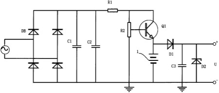
The figure is a schematic structural view of a smart water meter according to a preferred embodiment of the present invention.
Content Description
The utility model relates to the field of intelligent instrument control, in particular to a novel intelligent water meter.
Background of the invention
The smart water meter is a new type of water meter that uses modern microelectronics technology, modern sensing technology, and smart IC card technology to measure water consumption and conduct water data transmission and settlement transactions. In addition to recording and electronically displaying water consumption, it can also automatically control the water consumption according to the agreement, and automatically calculate the water fee for the water price of the stepped water price, and at the same time, it can perform the function of water data storage. Because the data transfer and transaction settlement are performed through the IC card, it is possible to realize the transition from the staff's on-site meter reading charges to the user's own payment to the business office.
Although smart water meters have many advantages, they also have some problems. One of the more obvious defects is that due to the power consumption of smart water meters, the batteries have to be replaced regularly. If batteries are not replaced in time, the electromagnetic valves may not be sufficient. The energy cannot be closed, resulting in loss of water. Moreover, replacing the battery with a frequency change will not only increase the user cost, but also cause environmental pollution. At the same time, frequent battery replacement operations may also cause component damage.
Therefore, it is necessary to propose an improvement plan that can solve the problem of replacing the battery with the frequency of the smart meter, saving the user cost, improving the service life of the smart meter, increasing the accuracy, and environmental protection.
Summary of the Invention
The main purpose of the utility model is to provide a novel intelligent water meter. The water meter can reduce the frequency of battery replacement, prolong service life, and at the same time protect the environment and improve the accuracy of the water meter.
The figure is a schematic structural view of a smart water meter according to a preferred embodiment of the present invention.
To achieve the above objectives, the technical solution adopted by the utility model is: a novel intelligent water meter including a microprocessor module, a flow monitoring module, an IC card reading and writing function module, a liquid crystal display module, a solenoid valve module, and a power supply module. The power supply module is connected with the microprocessor module and the electromagnetic valve module, and the flow monitoring module, the IC card reading and writing function module, and the liquid crystal display module are all connected with the microprocessor, characterized in that: the power supply module comprises an AC power supply, a rectifier bridge DB, Filter capacitors C1, C2, resistor R1, variable resistor R2, transistor Q1, rechargeable battery, diode D1, capacitor C3, Zener diode D2, and both ends of the AC power supply are connected to the two input terminals of the rectifier bridge DB, and are filtered. Both ends of the capacitor C1 are respectively connected to the two output ends of the rectifier bridge DB. The filter capacitor C2 is connected in parallel to both ends of the filter capacitor C1. One end of the resistor R1 is connected to the anode of the filter capacitor C2, and the other end is connected to the variable resistor R2. One end is connected, and the other end of the variable resistor R2 is connected to the cathode of the filter capacitor C2 and grounded, and the adjustable branch thereof is connected to the base of the transistor Q1. The set of the transistor Q1 is The electrode is connected to the other end of the resistor R1. The emitter is connected to the positive electrode of the rechargeable battery. The negative electrode of the rechargeable battery is connected to the other end of the adjustable resistor R2. The anode of the diode D1 is connected to the emitter of the transistor Q1, and the negative electrode is connected to the capacitor C3. The positive electrode, the negative electrode of capacitor C3 is connected to the negative electrode of the rechargeable battery and then grounded. The negative electrode of the zener diode D2 is connected to the positive electrode of the capacitor C3 and is used as the positive output terminal of the power supply. The positive electrode of the zener diode D2 is connected to the negative electrode of the capacitor C3. The negative output terminal of the power supply outputs a voltage U to provide power supply to the microprocessor module and the solenoid valve module.
Further, the smart water meter further includes an alarm module. The alarm module includes a resistor R3 connected to the output voltage U, a buzzer B connected to one end of the resistor R3, and a collector connected to the other end of the buzzer B. Transistor Q2, the base of the transistor Q2 is connected to an I/O port of the microprocessor module, and the emitter is grounded.
Further, the smart water meter further includes a tamper table module. The tamper table module includes a switch S1. One end of the switch S1 is connected to an interrupt input end of the microprocessor module, and the other end is grounded.
The utility model has the following beneficial effects: The utility model improves the power supply of the dry battery in the prior art to the use of an alternating current power supply for supplying power to the intelligent water meter. The alternating current power is converted into a direct current power supply through the rectifier bridge, and the AC-DC is removed by the filter capacitors C1 and C2. The fluctuating components in the conversion generate a constant value of DC power. By adjusting the resistance of the resistor R2, different sizes of DC power can be generated, and different volt-worth rechargeable batteries can be charged to meet the power requirements of different specifications of the smart water meter. Connecting the capacitor C3 and the zener diode D2 at the back end of the rechargeable battery can suppress the surge phenomenon and thus protect the internal components of the smart water meter.
The AC power supply can be used as the first power supply to continuously supply power to the smart meter, eliminating the trouble of frequent battery replacement due to power problems, and improving the environmental protection. During normal operation, the AC power supply will charge the capacitors C1, C2, C3 and the rechargeable battery while supplying power to the internal components of the smart meter. Once the mains power is cut off, the rechargeable battery will act as the second power supply for the internal components of the smart meter. When the rechargeable battery is powered down due to continuous operation, the capacitors C1, C2, and C3 will discharge. As the third power supply, the solenoid valve provides sufficient energy to close the valve, enabling it to perform microprocessing in time. The closing action issued by the module avoids the loss of water metering and improves the accuracy of the smart meter.
When the microprocessor module detects that the amount of water is insufficient, the collector and emitter of the transistor Q2 will be turned on, thereby prompting the buzzer to alarm, prompting the user to pay in time, which is convenient and effective.
When the water meter is in normal use, the switch S1 in the tamper-proof table module is disconnected, and the interrupt input of the microprocessor module is in a high state. Once the water meter is maliciously opened by the user and improper water operation is performed, the switch S1 is closed, making micro The interrupt input terminal of the processor module changes from high level to low level. The microprocessor interrupts the signal and immediately controls the closing of the solenoid valve to prevent the occurrence of user misconduct. The safety is good.
For more information, please download the full specification of the patent.
More information on the latest technology of meter technology patents, please continue to pay attention to [instrument patents]
Sand Conveyor,Belt Conveyor,Grain Transmit Conveyor,Grain Conveyor Belt
Xinxiang Zhenying Mechanical Equipment Co., Ltd , https://www.zhenyinggroup.com