ã€Abstract】 This article mainly introduces the construction of energy-saving building energy-saving supervision platform in a certain judicial bureau of Guangdong, and focuses on the Acrel-5000 building energy analysis management system software, and the intelligent energy-saving monitoring of distributed acquisition and centralized control management. system.
[Keywords]: office building; smart meter; building energy analysis
ã€text】:
1 Preface
China is currently the world’s second energy producer and consumer. The continuous growth of energy supply has provided important support for economic and social development. At the same time, the rapid growth of energy consumption has created a broad space for development for the world energy market. China has become an indispensable part of the world energy market. China’s development is playing an increasingly important and positive role in maintaining global energy security.
In China, building energy consumption accounts for more than 27% of total energy consumption, and it is still increasing at a rate of 1 percentage point per year. According to the statistics of the Ministry of Housing and Urban-Rural Development, the construction area of ​​newly built houses in urban and rural areas in China is nearly 2 billion square meters each year, of which more than 80% are high-energy-consumption buildings; existing buildings are nearly 40 billion square meters, and over 95% are high-energy-consuming buildings. The ratio of building energy consumption to total national energy consumption has risen rapidly year by year. To cope with the above situation, new buildings in China have basically been designed according to energy-saving standards. This proportion has reached 95.7%, but the proportion of energy-saving design standards implemented during the construction phase is only 53.8. %.
According to statistics, the total area of ​​office buildings and large-scale public buildings in China’s state agencies is less than 4% of the total area of ​​urban buildings, but the annual power consumption accounts for about 22% of the total urban power consumption in the country. The annual power consumption per square meter is ordinary residents. 10 to 20 times that of houses, 1.5 to 2 times that of similar buildings in developed countries such as Europe and Japan.
From this point of view, energy conservation and emission reduction are major issues that China must face and urgently need to solve in its current and future development. In fact, the 11th Five-Year Plan has set specific targets for reducing energy waste and reducing exhaust emissions. The Development and Reform Commission issued by the State Council and relevant departments have formulated the “Comprehensive Work Program for Energy Saving and Emission Reduction†to clarify that China will achieve energy-saving and emission reduction. The target mission and overall requirements.
For the long-term sustainable development of our country, for the energy security of our country, and for building our country into a harmonious and modernized civilized society, energy-saving and emission reduction is an established goal that must be accomplished. In order to achieve the above goals, as a building that occupies more than 1/4 of the total energy consumption, there is an urgent need to establish a complete energy monitoring system. In particular, a national government office building and large-scale public building energy consumption monitoring system must be established. It is a necessary measure for energy conservation and emission reduction.
2 system design basis and technical specifications
The building energy consumption monitoring system was designed and developed after the Ministry of Housing and Urban-Rural Development formulated the technical specifications of the “Energy Monitoring System for Offices of State Organs and Large Public Buildings†issued by the Ministry of Housing and Urban-Rural Development. Therefore, the design basis is sufficient, the technical standards are correct, and a reserved interface for energy saving and emission reduction is provided.
The technical specifications for the design of this system include:
1. Technical requirements of the Ministry of Housing and Urban-Rural Development
"Guidelines for the Energy Consumption Data Collection Techniques for Energy Consumption Monitoring Systems of Office Buildings and Large Public Buildings of State Organs"
"Technical Guidelines for Energy Consumption Data Transfer of Office Energy Consumption Monitoring System for Office Buildings and Large Public Buildings"
"Technical guidelines for the design and installation of sub-item metrology for energy consumption monitoring systems for office buildings and large-scale public buildings of state agencies"
"Technical Guidelines for the Construction and Maintenance of Data Centers for Energy Monitoring Systems for Offices of State Organs and Large Public Buildings"
"Code for the construction, acceptance and operation management of energy monitoring systems for office buildings and large public buildings of state agencies"
"Guidance Manual for Software Development of Energy Monitoring System for Offices of State Organs and Large Public Buildings"
2. National and industry-related standards
GB50052-2009 Â Â Â Â Supply and Distribution System Design Specification
DL/T 698 Â Â Â Â Â Â Â Energy Information Collection and Management System
MODBUS_RTU Multifunction Meter Communication Protocol
CJ/T 188-2004 household meter data transmission technical conditions
GB/T 19582-2008 Industrial Automation Network Specification Based on Modbus Protocol
GB 9254-1998 Radio disturbance limit and measurement method for information technology equipment
GB/T 17168-1998 Information technology equipment immunity limit and measurement method
GB/T 17626-1998 Electromagnetic Compatibility Test and Measurement Technology
3 Application examples of building energy analysis management system
A city-level judicial center in Guangdong covers an area of ​​85 acres, a total construction area of ​​92,000 square meters, an investment of 400 million yuan in construction, an institution building after completion, and a court of law for the district courts, procuratorates, bureaus, and political and law committees. System unit office use.
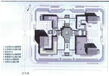
The project has 1 # (* Bureau), 2 # (Court, Procuratorate) two transformation and distribution room, the indoor distribution cabinet installed Ankerui 332 PZ series programmable smart meter. In order to realize real-time telemetry of power parameters, energy metering, and power report functions, the system uses the Acrel-5000 energy consumption monitoring and management system to achieve centralized management and centralized control, which solves the cumbersome task of on-site meter reading by on-duty personnel and the manual manual The problem of low efficiency and low data reliability caused by meter reading . Interface and built-in extensibility, can facilitate water, gas, and other energy consumption extended access monitoring, with less investment, concise and practical, to facilitate intelligent management advantages.
3.1 System Structure
The duty room of the Judicial Center is located on the 1st floor of the Transformer Room next to the office and is equipped with an industrial network switch; 13 buses are used on the site of the 2# power distribution room, and a 16-port serial server is used to connect the fiber through the optical fiber. To the switch on the 1# interior of the duty room; on the 13th bus of the 1# power distribution room, a 16-port serial server is used to connect to the switch in the duty room; then the data is transmitted to the back-end system through the LAN of the building.
Acrel-5000 energy consumption monitoring and management system topology is shown in Figure 1.
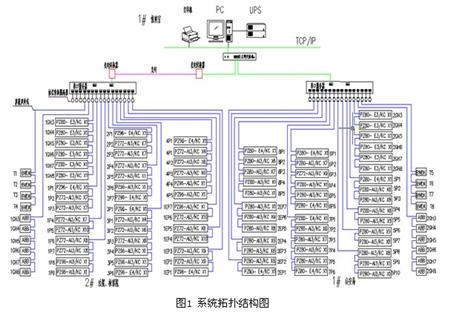
Acrel-5000 energy consumption monitoring and management system adopts a distributed structure, which is divided into functional or regional, modular design. The entire system is divided into three levels, namely the field level, the middle level, and the master level.
The main task of the field layer is to collect and measure the operating parameters of various distribution systems on the site, and transmit various data collected and measured to the monitoring system. The project mainly uses more than 300 sets of Ankerui PZ series programmable smart meters, which realizes the monitoring and management of more than 300 points on site. The above devices perform their own functions independently of each other, do not depend on the operation of the main control computer, and have an RS-485 communication interface. The detected electrical parameters and status signals are transmitted to the intermediate layer data processing in real time through the on-site RS-485 bus. Unit - Communication Server.
The middle layer is located between the field layer and the master layer, using a high-performance, embedded communication server. The communication server is responsible for the data collected at the field level through the network communication connection, data exchange and upload to the master control layer, which is the bridge between the master control layer and the field layer.
The main control floor is located in the duty room next to the 1#* office substation and distribution room, equipped with high-performance, high-reliability industrial-grade computers, UPS uninterruptible power supplies, and printers. The Acrel-5000 energy consumption monitoring and management system is installed on the main control computer. Through the software's man-machine interface and various control functions, it realizes the energy consumption monitoring and analysis management of the entire building power system.
3.2 Â Â Device parameter list
name
Model, specification
unit
Quantity
Note
Field device layer
Electricity meters, etc.
 
only
332
 
Station control management
Workstation host
EVOC IPC-810B
station
1
Yanxiang
monitor
22W "LCD Monitor
station
1
AOC
UPS power supply
C1K
station
1
SANTAK
printer
HP 1007 A4 format
station
1
HP
system software
Genuine Microsoft WINDOWS XP/SP3
set
2
Microsoft
Communication cabinet
8U wall mounted
surface
12
Local procurement
Console
Steel wood structure with a chair
set
1
Shanghai Xiangming
Energy Analysis Software
System Configuration Software Acrel-5000
set
1
Ankerui
Energy Analysis Software
Data Storage Software Acrel-dbSQL
set
1
Ankerui
Energy Analysis Software
Energy Management Software Acrel-EnerSys
set
1
Ankerui
Energy Analysis Software
Device Driver Software Acrel-Driver
set
1
Ankerui
Energy Analysis Software
Report Analysis Software
set
1
Ankerui
Network communication layer
Industrial network switch
TP-LINK (8 ports)
station
1
TP-LINK
Industrial Communication Isolator
I-7520R
station
32
æ³“æ ¼
Industrial Serial Server
NPORT5630-16 RS485 interface × 16
set
2
MOXA
Photoelectric converter
MIE-1102S
set
twenty four
Zhao Yue
Industrial switching power supply
KDYA-DG75-24
set
12
Huali
3.3 System Function Introduction
The on-site low-voltage power distribution system mainly consists of eight 10/0.4 kV distribution transformers and two emergency generators. This system is mainly responsible for the real-time dynamic monitoring of the low-voltage incoming line and the corresponding outgoing circuit.
The incoming circuit uses PZxx-E4/KC, which can measure three-phase voltage, three-phase current, active power, reactive power, power factor, frequency, active power, reactive power and other electrical parameters, and it has 4 circuits. Opto-isolated digital input contact and 2-way relay control output contact with RS485 communication interface.
The outgoing circuit adopts PZxx-AI3/KC, which can measure three-phase current, with 4 channels of photoelectric isolation switch input contacts and 2 relay control output contacts, with RS485 communication interface.
After entering the system through telemetry we can see the three-phase line voltage, current, power, energy and other electrical parameters of each loop . The remote signaling function is to realize the display of the operating status of the field devices, mainly including: switching of the switch, closing operation status and communication failure alarm, and an alarm signal will be issued when the circuit breaker is dislocated . As shown in Figure 2 below, the high-voltage power distribution system mainly monitors the operating status of the high-voltage loop. The red represents the closing and the green represents the opening. The three-phase current and the line voltage are displayed dynamically on the screen.

The low-voltage power distribution system of Fig. 3 mainly monitors the electrical parameters of the operating equipment, including the three-phase current, power, power, energy, frequency and other electrical parameters of the incoming line and the three-phase current of the outgoing circuit .

The system communication status chart can be used to view the communication operation status of each device in real time, as shown in Figure 4.

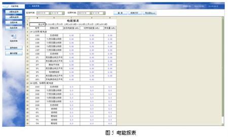
Remote meter reading function, complete the real-time remote collection function of each major circuit. According to the time period, the energy consumption of each loop can be queried and the energy report can be printed regularly. See Figure 5.
The trend curve can intuitively view the load operation of the loop and compare the energy curves between different time periods, as shown in Figure 6.

3.4 Implementation Effect of Energy Consumption Management System
After nearly one year of operation, the energy analysis management system in the office building has accumulated a certain amount of energy consumption data. The management personnel can use this system to perform real-time monitoring of the sub-items and power supply circuits in the building. The timely correction of the behavior of individual offices forgetting to turn off lights, air conditioning and office equipment during non-working hours. Through the statistical analysis of historical energy consumption data, the distribution of electricity consumption in the sub-systems of each building and the energy consumption of each department have been grasped. Acrel-5000 energy consumption monitoring and management system provides an objective quantitative basis for energy-saving management of office buildings in state offices.
4 Conclusion
Energy-saving and emission-reduction is a major issue that China must face and urgently need to solve in its current and future development. The successful application of this judicial center project proves that Acrel-5000 energy monitoring and management system provides a basic platform for real-time data collection and remote management and control of state offices and office buildings, and enables the automatic collection of building-specific energy consumption and automatic summary. And analysis, the system can obtain real-time energy consumption of large-scale buildings, and provide decision-making basis and reference for reducing building energy consumption and improving building energy efficiency; providing key data for further promoting energy statistics, energy audit, energy efficiency evaluation, etc. .
references:
[1] "Principles and Application Guide for Power Electronic Measurement Digital Meters", Ren Chengcheng, Zhou Zhong, China Electric Power Press
[2] Shanghai Ankerui Electric Co., Ltd. Product Manual. 2013.01.
[3] [2008] Circular No. 114 "Notice on Printing and Distributing the Technical Guidelines for the Construction of Energy Consumption Monitoring System of Office Buildings and Large Public Buildings of State Organs"
Aluminium Foil,Custom Aluminium Foil,Aluminium Foil Paper,Chemical Formula Aluminum Foil
Jiangyin Xinren Aluminium Technology Co.,Ltd , https://www.xraluminium.com