Abstract: When a fast edge signal is transmitted on the device under test, if there is a discontinuity in the impedance, a reflection occurs. Therefore, by observing the reflection phenomenon, we can find the discontinuities in the circuit under test, such as short circuit, open circuit, via, change of trace width and so on. This article describes high-resolution TDR testing and applications for everyone to understand.
Introduction When a fast edge signal travels on the device under test, reflections can occur if impedance discontinuities are encountered. Therefore, by observing the reflection phenomenon, we can find the discontinuities in the tested circuit, such as short circuit, open circuit, via, change of trace width and so on. People not only hope that TDR equipment can be used for impedance measurement of PCB traces, cables and other products, but also hope that TDR equipment can be used in chip failure analysis (FA) and circuit model extraction of high-speed circuit boards. When the tester needs to pinpoint the impedance discontinuity, he must have a high-resolution TDR device.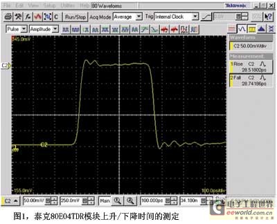
The resolution of a TDR device There are actually two important components within a TDR device. One part is a step signal generator, which can send a step signal with a very fast rise time. The other part is a high-bandwidth sampler that can receive, sample, and display the signal reflected from the DUT on the screen of the instrument. The industry often uses high-bandwidth sampling oscilloscopes as a platform for TDR test equipment.
The ability of a TDR device to discover or perceive the smallest (ie, shortest) impedance discontinuity is called resolution. Theoretically, the minimum impedance discontinuity that can be resolved (or referred to as perception) when a step signal is transmitted over the DUT is the distance the electrical signal travels on the DUT during the rise time of the step signal. Assuming that the rise time of a step signal is t, assuming that the transmission rate of the electrical signal on a material under test circuit is v, then the distance resolution l satisfies the following equation:
l=vt
Therefore, for a TDR device to obtain higher resolution, the step signal rise time of its step signal generator must be shorter.
At the same time, we should note that there is another important component of the TDR equipment, the high bandwidth sampler. When considering the resolution of a TDR device, the bandwidth of the sampler must also be taken into account. Samplers with different bandwidths have different own rise time indicators, and higher bandwidth samplers have faster rise times. The following empirical formula for the sampler's rise time and bandwidth can be scaled:
T=0.35/Bandwidth
When the sampler samples the reflected signal, it will affect the resolution of the TDR measurement due to the rise time of the sampler itself. When looking at the resolution of a TDR device, simply focusing on the rise time of a step generator or the bandwidth of a high-speed sampler is incomplete. Therefore, in the test specification of the PCB industry IPC-TM-650 test manual, the concept of the system rise time of the TDR equipment is proposed, which is denoted as Tsys. Tsys characterizes the overall characteristics of a TDR device. Tsys can be measured directly on the TDR device by terminating a shunt on the interface of the TDR device and measuring the rise/fall times of the waveform acquired by the TDR device. The measured result is the system rise time and fall time. Figure 1 shows the system rise/fall times measured for the Tektronix 80E04 TDR module.
We can calculate the resolution of the TDR device L by the system rise time of the TDR device. As the following formula:
L=(v*Tsys)/2
Because we measured Tsys after receiving the reflected wave with a high-speed sampler, it can be said that the step signal has been “walked†twice “once and back†on the DUT. So you need to divide by 2 when calculating the resolution. Taking the surface traces of the FR4 PCB board (v is about 5.5inch/ns) as an example, a resolution of about 2mm can be achieved using the 80E04 TDR system. The test resolution of the 80E04 TDR module is already high enough for PCB board impedance testing and cable impedance testing.
However, the 2mm resolution of the PCB vias, the open circuit inside the chip, and the short circuit is slightly insufficient, requiring a higher resolution of the TDR device. The vias of the PCB are millimeter-sized. The length of the traces inside the chip is between a few millimeters and a centimeter. Therefore, the resolution of the TDR equipment is better than 1mm to complete the extraction of the circuit model of the PCB via hole and the short-circuit and short-circuit positioning of the internal wiring of the chip.
High-resolution TDR probes are part of the TDR test system. When performing TDR probing, we must inject a fast step signal into the DUT to complete the test. The tool is the TDR probe. Figure 2 is a single-ended probe commonly used for TDR testing. It consists of a probe tip, probe cable, and antistatic module control wire. The probe has a nominal bandwidth of 18 GHz. When the probe is connected to a TDR test equipment, the system bandwidth is limited to less than 18 GHz, and the resolution of the TDR test is reduced. The probe is fully qualified in the trace characteristic impedance test of the PCB board, but it is incapable of doing the PCB trace via hole measurement and chip failure analysis test. It can be seen that if we simply have a high-resolution TDR device is not enough, we also need a high-bandwidth TDR probe.
There are many factors that affect the bandwidth of the TDR probe, such as the length of the probe cable, the size of the probe tip, and so on. In general, the longer the probe cable is, the greater the attenuation of the high-frequency signal and the lower the bandwidth. The larger the size of the probe tip, the lower the bandwidth.
Therefore, a simple but very effective and necessary measure to increase the detection bandwidth is to shorten the probe cable as much as possible without using the probe cable.
The TDR module's extension cable allows the module to be as close as possible to the DUT, reducing the impact of the TDR probe's cable on the probe bandwidth.
Because of the large size of the TDR test module, it is inconvenient to detect it by hand. Therefore, a module similar to a machine tool is used to fix the module, and the mobile DUT closes to the TDR module to complete detection. People call this device similar to a machine tool ProbeStation.
Using the TDR module extension cable and ProbeStation can maximize the performance of existing TDR equipment. The resolution that can be obtained with the 80E04 TDR module is only about 2mm, and still can not meet the needs of high-resolution TDR users.
Solutions for higher resolution TDRs To fundamentally improve the resolution of TDR tests, it is necessary to look for faster step generators and higher bandwidth samplers with rising edges. Before that, people have found a solution consisting of multiple independent instruments.
In the combined scheme, a high-resolution step-by-step signal generator (4022) with Picosecond high-bandwidth sampler 80E06 was combined into a set of high-resolution TDR test systems, see Figure 3. The test system is composed of a high-speed step signal generator Picosecond4022 combined with a sampling module 80E06 of 70GHz bandwidth. The nominal system rise time reaches 9ps, and the ultra-high TDR test resolution can be obtained.
80E10 High-Resolution Test Module Although the high-resolution TDR combination scheme can obtain significantly higher test resolution than the original 80E04 scheme, there are also some problems. For example, for the ease of use, the combination scheme cannot be separated from the complicated cable connection, and it is difficult to detect the DUT; when reading the impedance measurement, the value read by the combination program on the instrument can only be the voltage value and cannot directly obtain the impedance value or Reflectance values; compensation, calibration, and consistency of test instruments. The two components of the combined solution come from different suppliers, so there are more or less problems with temperature compensation, calibration, and consistency of the instrument. The combination scheme is more like a scientific research device than a commercial test device. Implementing an integrated high-resolution TDR measurement from a single vendor remains the tester's expectation.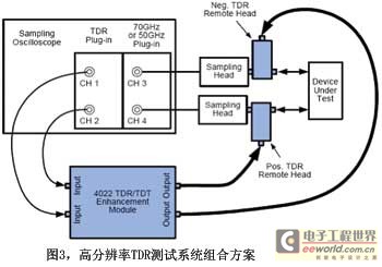
Tektronix recently introduced the new high-resolution TDR module 80E10, 80E08. The 80E10 module's system rise time is as high as 15ps (typical).
Overcoming Multiple Reflections in TDR Tests When testers use high-resolution TDR equipment to perform failure analysis on a chip or perform TDR testing on a high-speed PCB backplane, they may encounter various complexities within the chip or the PCB backplane. The multiple reflections caused by the wiring conditions make it difficult to find the location of the short circuit/breakpoint. The multiple reflections are shown in Figure 4.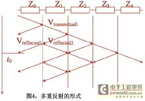
When there are multiple impedance discontinuities on the trace being tested, for example, if the trace of the DUT contains multiple corners or layers, then the signal will reflect when passing through every two adjacent impedance discontinuities. The reflected waveforms will be superimposed and the waveform reflected on the instrument will be chaotic. The presence of multiple reflections causes the tester to confuse the test waveform results with the DUT traces.
If dedicated TDR software is used, the original TDR test waveforms are segmented according to reflections, and the effects of multiple reflections on the test can be corrected by deconvolution (De-convolution/deconvolution) algorithm to restore true Look. Obtain impedance test results that are consistent with the DUT trace conditions. Figure 5 is a comparison of the waveform after correction of multiple reflections by software with the original waveform.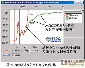
The green waveform is a test waveform with significant multiple reflections, and the red waveform is a software-corrected waveform. From the original waveform, we can't find the end point of the tested trace. According to the common sense of the TDR test, we know that the endpoint of the trace should be on the waveform and it should rise rapidly to infinity, while the green waveform can't find the end of the trace. Therefore, the tester could not tell that the test result corresponds to the condition of the tested cable, causing great misunderstanding. The software-corrected red waveform allows the tester to easily find the end point of the trace to be tested and correlate the test result with the trace being tested.
Summary TDR equipment with a typical system rise time of 28ps has reached a resolution of about 2mm on the common material DUT, which is entirely suitable for conventional test applications such as characteristic impedance testing of PCBs and cables. When testers need to achieve higher resolution requirements, not only do TDR test equipments have to be maximized in terms of detection methods, such as the use of extension cables, ProbeStation, etc., but also TDR equipment that requires higher system rise time, fundamentally Improve system test resolution. In many high-resolution TDR test situations, multiple reflections are common. Using TDR test software to correct the original waveform with multiple reflections is a very effective method of analysis.
Steel shearing machines are used by manufacturing companies to cut sheet metal, as well as other materials and workpieces, with a straight blade. The sheet metal is secured below the cutting blade, after which the cutting blade drops down to cut through it. There are many different types of shearing machines, however, one of which is an Alligator Shear. Alligator shears contain a straight-bladed cutting tool as well, but they feature a unique alligator-like design that distinguishes them from other shearing machines.
Steel Shearing Machine, Steel Shear, Steel Alligator Shear, Steel Guillotine Shear
Jiangyin Metallurgy Hydraulic Machinery Factory , https://www.eco-balers.com